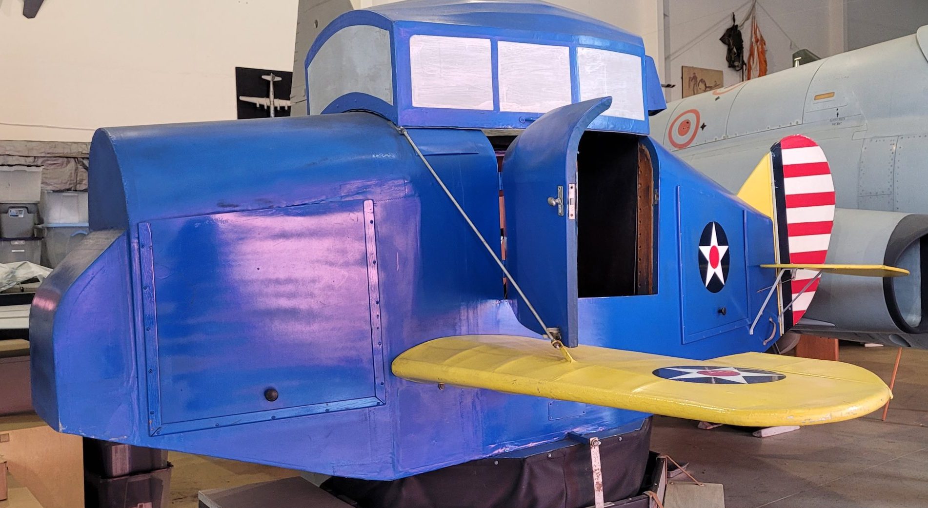
 The link trainer pictured is a 1942 Model C-3, the term Link Trainer, also known as the “blue box,” is commonly used to refer to a series of flight simulators produced between the early 1930s and early 1950s by Edwin Albert Link, based on technology he pioneered in 1929 at his family’s business in Binghamton, New York. The original Link Trainer was created in 1929 out of the need for a safe way to teach new pilots how to fly by instruments, using a radio range for determining an airplane’s position in instrument flight conditions and a subsequent let-down to a field for landing. This primary navigation system was comprised of sparsely located Adcock low-frequency range transmitters. Each facility consisted of four legs which could be used as “beams” for navigating either to or from a station on the airways or for shooting low approaches for landing. Each range station emitted audio signals comprised of four quadrants. Two quadrants provided a Morse Code signal of “N” (dash-dot) while the opposing quadrant emitted an “A” signal (dot-dash). Each quadrant overlapped precisely to provide a three-degree leg or beam by meshing the two audio signals to provide a continuous dash or “on course” monotone signal.
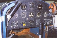 These simulators became famous during World War II, when they were used as a key pilot training aid by almost every combatant nation. More than 500,000 US pilots were trained on Link simulators, as were pilots of nations as diverse as Australia, Canada, Germany, Great Britain, Israel, Japan and the USSR.
The Link Flight Trainer has been designated as A Historic Mechanical Engineering Landmark by the American Society of Mechanical Engineers
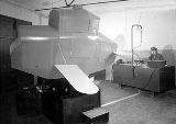 The Link was mounted on a base which permitted the trainer to turn, tilt and bounce as the instructor (who sat at a desk outside the trainer) created rough air and put the pilot through simulated instrument flight conditions. An operator sat at the desk and transmitted radio signals which the “pilot” in the link heard though his ear phones. The pilot “flew” the link through various turns, climbs, and descents, and the link’s “course” was traced in red ink by the remote “bug” on a map on the table. After a flight was completed, the pilot could study the red-line course to determine his what he might have done incorrectly. There was no AIR CONDITIONING in these trainers… and on a hot west Texas day, it got pretty hot inside this ‘box’. Many a young trainee almost crashed and burned–not from lack of flying skills, but from the heat!
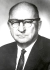
In the late 20’s Edwin A. Link learned to fly while working for his father in Binghamton, New York who manufactured organs and pianos. Because of the economic depression at that time, flying lessons became too costly. Link got the idea to shorten the expensive flying lessons by learning rudimentary piloting skills using a ground aviation trainer. Drawing from his expertise in air-driven pianos and pipe organs, Link used organ parts and compressed air to build the first flight simulator.
In 1928, Edwin A. Link left his father’s organ building business to begin work on a “pilot trainer.” He designed the trainer using suction through fabric bellows to cause motion. Organ bellows and a motor provided the means for the trainer, mounted on a pedestal, to pitch, roll, dive and climb as the student “flew” it. In 1931 he received a patent on his “pilot maker” training device.
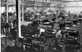 Most of his first sales were to amusement parks. In the beginning there was very little interest by the flying community in Link’s trainer. Initially the trainer was meant for instruction of visual flight, but in 1934, after a series of tragic accidents while flying the air mail, the Army Air Corps bought six Link trainers to assist in training pilots to fly at night and in bad weather, relying on instruments. The second customer for the Link trainer was the Japanese Imperial Navy in 1935. Many Japanese pilots were trained in these Link trainers and used their skill and knowledge in fighting the American planes in World War II.
The need for pilots with instrument training in World War II resulted, by the end of the war, in Link delivering 6,271 Link trainers to the Army and 1045 to the Navy. The Link trainers were also used by 35 foreign countries. Although Army Air Force’s aviation cadets flew various trainer aircraft, virtually all took blind-flying instruction in the Link.
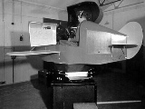 Movement of the trainer is accomplished by vacuum operated bellows, controlled by valves connected to the control wheel (or stick) and rudder pedals. An instructor sat at the desk and transmitted radio messages which the student in the Link heard through his earphones. Inside the “cockpit”, the student relied on his instruments to “fly” the Link through various maneuvers while his navigational “course” was traced on a map on the desk by the three-wheeled “crab”. Slip stream simulators gave the controls the feeling of air passing over control surfaces, and a rough air generator added additional realism during the “flight”.
The Link Trainer holds a significant place in aviation history. It was the first true flight simulator, and provided safe instrument training to hundreds of thousands of student pilots during the 1930s and 40s.
Restoration Program:
In 1993, the Western Museum of Flight (WMOF) initiated the restoration of a 1942 Model C-3 Link Trainer. A crew of WMOF Volunteer Docent/ Restorers staffed the project. They had at their disposal an inventory of donated obsolete and nonfunctioning parts of 1940’s era Link Trainers, that had been accumulated by the museum over several preceding years. This inventory consisted of: two bases, two octagons, an almost fully equipped fuselage, two blind flying hoods, an almost complete set of Link Trainer operation, overhaul, and maintenance technical manuals, and a sufficient amount of spare bellows, valves, turning motors, telegon transmitters, and instruments.
For the first phase of the project, the crew tore down the existing components and meticulously drew up scale drawings that would be used to rebuild the trainer and its various mechanical, electrical, and pneumatic systems. All of the major valves, linkages, tubing, bellows, and instruments were diligently taken apart, cleaned, put together again, and/or fabricated per the technical orders in the Link maintenance and overhaul manuals. The highly labor intensive, time consuming, and skilled work would require two years to accomplish. During this period, the process of putting together and completely rewiring the Link’s base, central column, vacuum compressor, and main electric panel were accomplished. In addition, the Link’s octagon with its master climb/dive and banking bellows was completely restored and work was initiated on the restoration of the Instructor’s Desk, its radio and automated flight tracking device.
In January 1995, the restored octagon was mounted to the Link’s base. Once completed, the base was fully restored with its now functioning vacuum compressor, wind/drift motor, and main electric panel. Work now progressed rapidly on the restoration of the Link’s fuselage. This required rebuilding the entire frame of the fuselage on the octagon. Much of the original frame was used, but many sections had to be completely rebuilt from scratch, utilizing the great scale drawings that had been made during the tearing down of the original and specifications laid out in the technical manuals.
In March 1997, restoration of the Link’s fuselage was completed. With the fuselage now sitting on the Link’s octagon, the restored components were then carefully reinstalled. This included all the major and minor valves, bellows, metal and rubber tubing, rough air generator, linkages, springs, telegon transmitters, turning motor, rudder pedals, control stick, altitude and airspeed vacuum cans, vibration motors, air dampers, cockpit lights, air circulating fan, and pilot’s radio. Although most of the restored components were used, some parts had to be fabricated on the spot. Once again, all this was done per the technical manual’s specifications, aided by the fine scale drawings made during the first phase of this project.
The next step was the restoration and installation of the Link’s instrument panel. The restored panel now contained a fully functional magnetic compass, gyro-horizon indicator, altitude meter, airspeed meter, turn and bank bubble, climb and dive indicator, engine rpm meter, clock, radio beacon, glide path indicator, fuel gauge, on/off switch, pitot tube heater switch, and fuel switch.
In July 1997, the time consuming re-calibration and testing of all of the Link’s major and minor valves, electrical transmitters, mechanical linkages, vacuum chambers and air dampers was completed. The partially restored pilot’s seat was then installed in the cockpit. Now, with one of the crew seated in the cockpit, the Link was given its first full powered systems test per instruction in the Link’s technical manuals. For all intents and purposes, the Link performed beautifully, flying level, banking and turning, climbing, diving, and stalling. A sign was affixed to the fuselage announcing to all who viewed it that the Link had successfully had its “First (post full restoration) Flight” on 3 July 1997.
In October 1997, California’s Santa Maria Air Museum donated a usable set of Link Trainer wooden framed, cloth covered wings, with movable ailerons, and wooden tail with movable rudder and elevators. Restored Wings, Elevator and Rudder
In November 1997, disaster struck the project. Arriving at the Museum to start work, the team found what they thought was sawdust on the floor, outlining the Link’s fuselage and base. Upon close inspection they also found several small piles of this “sawdust” inside the Link’s fuselage.
It was finally deduced that evidently long dormant termites in the old wooden framework of the fuselage had awakened and become active again. The entire wooden fuselage frame and floor were starting to crumble. This required a complete teardown and removal of all the painstakingly installed Link components. The affected fuselage was then removed from the octagon and destroyed. Luckily the octagon had been spared, but, as a safety measure, it was inspected and thoroughly treated with a termite inhibiting spray. the Link’s Instructor’s Desk and Blind Flying Hood/Canopies were inspected and treated.
In February 1998, March Air Force Base Air Museum provided a usable Link Trainer fuselage. This fuselage was found to be in fairly good shape. It had been denuded of all of its internal hardware, access doors, seat and backrest, but would only need a small amount of repair to bring it back into shape. It was completely inspected for signs of termites. The fuselage was quickly cleaned up, treated, mounted, and restored. Once again all of the required restored hardware, electrical, mechanical, and pneumatic systems were installed in the fuselage.
By year’s end, 1998, the work was finally completed and the newly restored second Link fuselage was installed in a jury rigged paint booth within the WMOF hanger and painted in the 1940’s style Army Air Corp distinctive blue colored enamel. Once again all the Link’s systems were re-calibrated and tested and the Link performed per specifications.
In 1998, the Link’s wings and tail assemblies were fully restored. The wing’s frames were repaired as needed and their cloth coverings patched and sealed. The wooden tail assemblies were cleaned and sanded. The wing’s ailerons hinges, brackets, and cables, along with the tail’s rudder and elevator’s hinges, cables, and brackets, were then restored to full working order. These assemblies were then painted in the 1940’s style Army Air Corp trainer distinctive yellow enamel. The restored wings and tail were installed on the Link’s fuselage. A new fixture had to fabricated to attach to the restored control stick assembly that would take, secure and activate the wing’s ailerons, when the stick was moved from its center position to the right or left. This was machined from a solid block of aluminum and when fitted, performed its required function perfectly. Now the Link began to look like a real little airplane.
During this year the restoration of the Link’s Instructor’s Desk and radio were completed. Also restored was the electrical and mechanical linkages from the desk to the Link’s base. When the Link was operated, the desk’s automatic tracker traveled across a copy of a 1940’s era flight map on the desk top, inking a dotted line to show the direction the Link was “flying”. Remote instrument’s on the desktop displayed the Link’s simulated attitude, airspeed, climb and dive angles on its respective meters. The desk and its remote instrument cabinet were painted the 1940’s era Army Air Corp olive drab colored enamel.
In 1999,the Link’s Blind Flying Hood/Canopy were completely restored . All the old, rotted cloth covering had to strip off and the wooden frame cleaned and strengthened . It was then recovered with aircraft linen, hot ironed , primed, and finally repainted in its 1940’s era Army Air Corp trainer blue enamel, with silver colored false windows. After installation of the hood, newly acquired 1942 era Army Air Corp aircraft roundels were affixed to the wings with red and white strips on the rudder. Small red “NO STEP” and “NO PUSH” caution signs were painted on the Link’s wings and rudder.
In June 1999, the Link’s metal-framed base was then fitted with pegboard cover panels and painted with a black enamel. A black cloth skirt was fashioned and affixed to the fuselage base and anchored to the octagon. The covering protected the major climb, dive, and bank bellows. The Link was now officially completely restored, displayed in all its bright colors. Visitors to the museum could now see the Link, as it would have been set up in a typical World War II Army Air Corp training building. Its Instructor’s Desk showed its radio, in its partially opened center drawer, an aerial flight map positioned under its Automatic Tracker, and its Instructor’s earphones and microphone displayed on their holder awaiting use by the Instructor.
February 28, 2000, disaster struck again. While moving the Link from an off site location it was inadvertently dropped. The entire nose section of the Link’s fuselage, just forward of the instrument panel, was ripped away. Both wings and one side of the stabilizer were also damaged. Due to the shock of the fall, all of the Link’s major valves were wrenched from their settings and severe damage was done to the sensitive telegon transmitter system that activated the airspeed and engine rpm indicators.
June 2000, restoration was started to repair the damage.The nose of the damaged Link was replaced with parts taken from another fuselage. The wings and tail were again restored. Once again the Link’s systems were reset, re-calibrated, and tested.

